|
|
 HOME PAGE
 PIXIE
PIXIE DASH FREE
Making DASH FREE faster Once you have made your DASH FREE micromouse, you are likely to find that, although you can make it follow a straight line very quickly the corners represent a bit of a problem. Some ideas to improve the control of your mouse are:-
a) Minimise the moment of inertia of the mouse about its turning centre. What this means is that every part of the mouse, especially heavy items such as the batteries, should be as close as possible to the point midway between the wheels. This will mean that the mouse can start turning very quickly and, probably more important, stop turning quickly.
b) Improve the sensing system. When the mouse reaches a corner, it will detect the corner as soon as the inner sensor leaves the line. It will continue to detect the corner even if the mouse goes quite a long way over the line as long as it doesn't reach the mark for the next line (white square on the mat). This makes the mouse very good at detecting the start of the corner.
Detecting the end of the corner when the mouse should straighten up for the next straight is more of a problem. The mouse cannot see that it should straighten up until the sensor is back on the line. At this time the mouse will be turning very quickly and its momentum will tend to keep it turning. If it hasn't straightened up before the sensor comes off the inside of the line, it will keep going round in circles!
One technique is to make the sensor "see" a much wider area. This can be done by adding multiple LEDs to the sensor circuit. See here for more information on the sensors.
Using an area coverage sensor, you can make the mouse "see" the line over a width of maybe 100 mm (it depends on how you make the sensor circuit) instead of the 50 mm width of the tape.
c) Another problem with making DASH FREE go fast is the trimmers. It is difficult to set these with great precision. You could replace the speed setting trimmers with multi-turn versions. Something like a 500R Bourns 3296Y (Farnell part number 348-089) will make speed setting less fiddly. DASH FREE 99s are supplied with multi-turm pots as standard.
d) Braking. With the standard DASH FREE there is no braking for corners. The inner wheel simply free-wheels to a stop when the corner is detected. As the inner sensor cannot be more than 250 mm in front of the wheel because of the size specification in the rules, this is a serious limitation on the speed that can be used down the straights.
One way of adding braking to the inner wheel is to put a P channel power FET across the inner motor connections. When braking is required the FET can be turned on and this will give a path for the current generated by the motor spinning. This current will give a strong magnetic braking effect and cut the braking distance dramatically.
I use a RFP10P03L (Farnell part number 516-430). The source should be connected to battery positive. The drain should be connected to the collector of TR2 and the gate should be connected to the drain of FET1. This will ensure that the FET is turned on when FET1 is turned on; i.e. when the sensor is turned off.
You should remove diode D2 to avoid the possibility of the brake coming on while the motor is being driven.
You should only do this braking modification for the inner motor.
You should find that this reduces the braking distances by a factor of at least 2 depending on the weight of your mouse.
e) Batteries. You can add more cells to give a higher battery voltage. I don't recommend that you go much above 9 volts (6 cells) if you try this. You can try using AAA cells instead of AA cells to reduce weight.
One problem to address is the type of cell chosen. Primary cells, especially in AAA size may have problems delivering the high currents needed by the inner motor when powering away from a corner. NiCd cells may make a faster mouse despite having a lower cell voltage as their internal resistance is low.
DON'T USE NiMH cells unless they are rated at at least 4A discharge current (8A if you use a 9 volt stack). The batteries must be rated for the stall current of the motors.
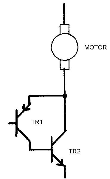
f) Less voltage drop. The complementary darlington TR1 and TR2, combined with the drops across the steering diodes etc. mean that the motor "loses" about 2.5V from the full battery voltage. This can be reduced by changing the circuit a little and adding a couple of resistors.
The original circuit used an emitter-follower circuit where the voltage at the emitter of TR1 was held about 0.6 volts above the voltage on the base of TR1. TR2 collector could not go below the voltage on the base of TR1.
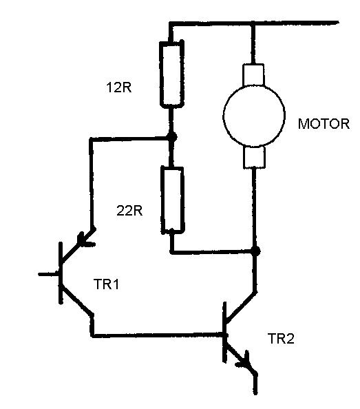
This new circuit has two resistors across the motor acting as a potential divider. The voltage at TR1 emitter is now approximately a third of the voltage across the motor. It is this voltage that is held about 0.6 volts above the TR1 base voltage. TR2 collector can now swing virtually all the way down to battery negative.
The resistors can be 1W types.
This modification should not be used on the older DASH FREE kits unless the multi-turn trimmer modification is also done or the trimmers will be much too sensitive. It is all right on DASH FREE 99s.
The modification will allow you to go faster on the standard batteries. You may find that you no longer need the weight of extra cells in the battery.
Please email comments and your own ideas for speeding up DASH FREE to:- Duncan@swallow.co.uk