|


|
|
|
|
|
|
|
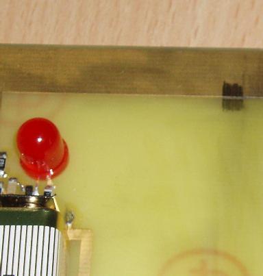
Use the pencil to draw a line across between the contacts. The LED will light according to the resistance of the connection. You will need to scribble across the join where the line meets the contact to ensure a good connection. An area 5-10 mm square is sufficient.
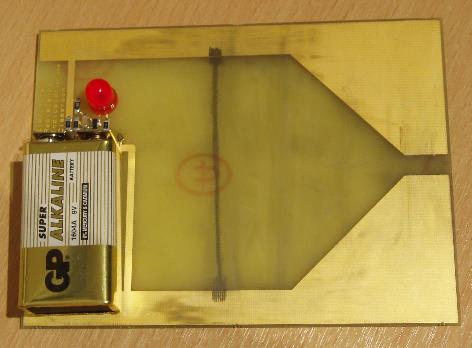
Now you can join the scribbles with a pencil line. A single stroke may have minute cracks in it that stop the current so you will probably have to go over the line several times. A continuous line as shown will light the LED fairly dimly.
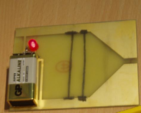
If you make the line wider, the LED will become brighter. If you add a second line, there will be another path for the current and the LED will be brighter.
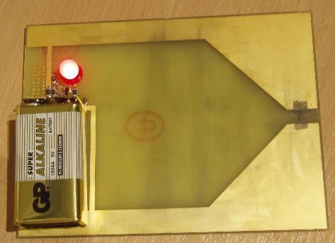
If you use a shorter line, between the wide contact areas, the LED will be brighter.
You can try out different shapes in the area between the contacts.
The rules are:
If there is no path between the
contacts the LED will be off. The wider the track, the
brighter the LED. The shorter the track, the
brighter the LED. The thicker the track (lots of
layers of pencil), the brighter the LED.
Lower electrical resistance makes the LED brighter.
Note that people conduct electricity! Only observe the LED brightness when your fingers are clear of the contacts.
You can remove the pencil lines using the eraser provided. Other soft erasers will also be suitable but do not use very abrasive types as you will remove the gold plating from the contacts.
You can use other pencils apart from the one provided. In general, softer pencils (e.g. 7B) will give lower resistance (brighter LED) and harder pencils (e.g. HB or 2H) will give higher resistance (dimmer LED). Do not expect coloured pencils or crayons to conduct electricity.