|
|
Background
Swallow Systems has made small commercial robots (PIP, PIXIE) for educational use since 1989. We have now started to use this technology in the IEE Micromouse Championships (DASH-1, DASH-2, DASH FREE). This note is to help those who want to know how we do our wall and masking-tape sensing.
Description The S4282-51 is a photo IC that contains nearly everything you need for a simple reflected-light sensor. All you add for the simplest sensor is an LED to provide the light.
The S4282-51 looks like a tiny transparent four-legged DIL I.C.. The four connections are +VE and -VE supply pins, LED constant-current drive and digital output.
The S4282-51 pulses the LED at about 7kHz. Inside the device is a photodiode that senses the light falling on the device and passes a corresponding signal to the rest of the circuitry. The signal is filtered and only signals that are effectively phase-locked to the pulse drive generate a response.
This makes the S4282-51 very tolerant of ambient light. Both DASH-1 and DASH-2 will operate on a sunlit maze with shadows on it. They are tolerant of conventional fluorescent lights but may be upset by modern electronic ballasted ones; I haven't tested them in these circumstances.
One form of light that does cause problems is from LEDs driven by other S4282-51s. You will need to take care of light pollution from these. There may be other sources of pulsed visible or infra-red light. I imagine light shining through a rotating fan could generate suitably modulated light.
The S4282-51 operates from supply voltages betwen 4.5 and 12V.
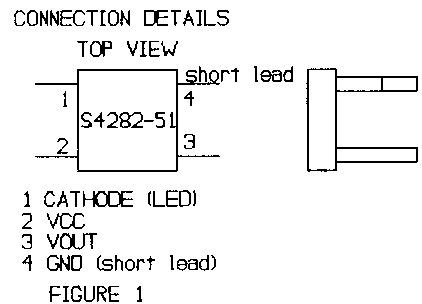
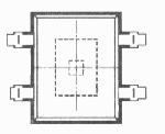
Practical considerations The first thing to get right is the connection details. These are shown in figure 1 looking from the top (active) side. Pin 4 is the short lead. It is a good idea to physically test that this is connected to GND to check your construction.
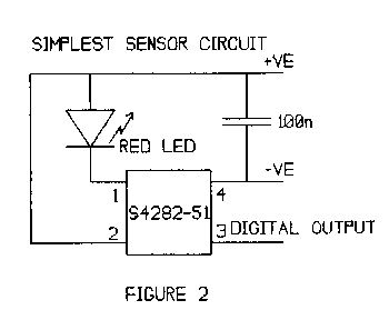
The simplest circuit is shown in figure 2. I always put a 100nF capacitor across the supply pins of the S4282-51 to give some measure of EMC protection. This is particularly important on Micromice sensors as they are typically mounted on longish leads away from the main PCB.
The red LED can be an infra-red type for the best match to the sensor characteristics. I don't use these as I want to see where the light is going. I use a Hewlett-Packard HLMP4101. This is a bright narrow-angle visible red LED. It projects a beam only some 1-2 centimetres across at a range of 10 centimetres.
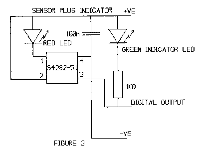
I always add an indicator LED so that I can tell when the sensor is on without recourse to connecting test equipment. The circuit for this is shown in figure 3. The green LED can be a cheap commodity type from any supplier. It does not need to be shielded from the S4282-51 as it is not being pulsed.
When you build your first sensor it is worth mounting the red LED on extended leads. This will allow you to completely shield the LED from the sensor to check the off condition and also shine it directly onto the active surface of the sensor to check the on condition.
Debug The first thing to check is the supply current. Using the circuit in figure 3, this will be less than 25mA if all is well. There is a large tolerance on the duty cycle and amount of drive current to the LED so it may be much less than this when the green LED is off.
The next check is that the red LED is on. Then you can do a functional check. If you have an oscilloscope you can check that the LED cathode is being pulsed. During the on condition it will be about 1.5V below the supply voltage. During the off condition the voltage will be partly determined by the ambient light going through the clear case of the LED as it behaves as a photodiode.
The on time is about 8usec. the pulse repetition period is about 130usec. There is a large tolerance on these times.
The most likely problems are the normal ones of dry joints, badly cut stripboard tracks and missing connections but there are a range of problems caused by optical effects.
Controlling the light You may have a problem with the sensor not turning off. This can be caused by stray light from the LED reaching the sensor by unexpected routes.
Although the LEDs that I use are narrow-angle, they do emit quite a lot of light out of the sides and the back.
I use two main techniques for avoiding this problem. The easy one is a suitable rubber grommet pushed over the LED to give very effective shielding of the light from the sides of the LED.
The other technique is to use Tipp-Ex. This is simply painted on to the LED to keep the light in. You will probably need several layers and the best place to do this is in a darkened room where you can clearly see where the light is leaking from. Unfortunately wet Tipp-Ex is not a good insulator so you will need to be careful not to blow up the electronics if you paint it on when power is applied.
The sensor circuit can be built in a very small space. The height of the LED can be a problem. I have not found suitable surface-mount LEDs so in one case I drilled a hole through the stripboard and mounted the LED through the board. This saved me some millimetres.
Area coverage In some circumstances you need a sensor that will detect a wall over a range of positions. On DASH-2 I need to detect whether a wall is too close over a range of some 0-35mm. At 40mm the wall is in the correct position so we must not detect it as "too close" there. We needed vertical sensors working off the top of the wall to give this kind of discrimination.
We could have used several sensor circuits ORed together but at £5.11 per sensor this was too much.
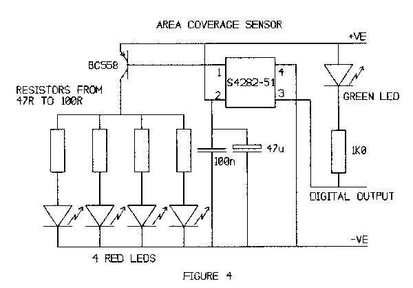
The solution was to use several LEDs driven from one S4282-51. Each LED projects a small spot of light onto the top of the wall. Provided that at least one spot is on the wall at all positions that you want to detect, the sensor will get enough light to detect the wall.
The circuit I use is shown in figure 4. This uses 4 LEDs. The LED output can be tailored to suit their individual distances from the sensor by altering the current limiting resistors.
It is worth running at the lowest effective LED current both to increase battery endurance and also to minimise the amount of modulated light sprayed around your mouse.
You should ensure that the sensor is far enough away from the wall so that it can "see" the reflected light. The S4282-51 responds well to light at up to 30 degrees from the normal.
Long range Sometimes you need to detect a wall at long range. Both DASH-1 and DASH-2 use long range horizontal sensors to detect a wall before using short-range vertical sensors to get the correct distance from the wall.
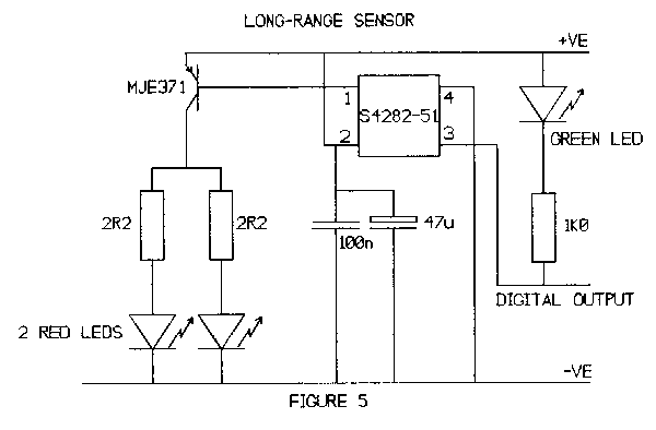
I do this by driving the LEDs very hard and using 2 or more LEDs aimed in the same direction. A typical circuit, actually used on DASH-2, is shown in figure 5.
The full LED cathode drive current drives the base of a PNP power transistor. The transistor provides peak currents of the order of 0.5A to each LED. This overdrives the LEDs but I am happy with a shortened operating life.
The 47uF electrolytic capacitor is absolutely necessary. The large LED currents will cause an large voltage drop on the leads back to the battery if there is no local energy storage. The transistor does not need a heatsink.
With two HLMP4101 LEDs this circuit gives a range of about 80mm on DASH-2. You will get longer range by adding more LEDs but the effect is not at all linear.
Range approximates to the radar equation where it varies as the fourth root of the light power. This means that doubling the range needs 16 times the power. To put it another way, if 2 LEDs give a range of 80mm, you would need 32 LEDs to get a range of 160mm.
Wih long-range multiple LED sensors, you should take care to align the LEDs carefully, It is no good having a long-range wall sensor if it is pointing at the floor!
Schools competition The requirements for the schools competition are somewhat different. Here you need to detect the difference between the amount of light reflected from white masking-tape and from the background black paper. The contrast ratio is low but it is sufficient if you take care to avoid direct reflections.
You should arrange the LED so that if the surface was a mirror it would not shine on the sensor chip. This ensures that the sensor works from the colour of the surface rather than how shiny it is.
You also need to accurately adjust the sensitivity of the sensors. This can be done by setting the height of the sensor and LED above the surface but this is not always convenient.
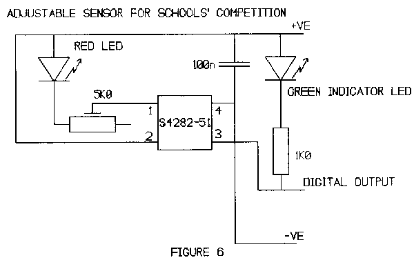
Another method is to adjust the LED current. Figure 6 shows how we do it on DASH FREE. The 5K0 trimmer can reduce the LED current to a level suitable for the conditions.
You will need to set the threshold accurately as the S4282-51 has hysteresis. Typically the light level must fall to 65% of the switch-on threshold to turn the device off. This takes up a lot of the available contrast ratio.
Sensor positioning Once you have experimented with making sensors you will need to think about the number of sensors needed and where they should be placed.
DASH-1 uses 6 sensors. Therer are three horizontal long-range sensors to detect if a wall is present at each side or in front and three short-range vertical sensors to detect that the mouse is at the correct distance from that wall.
This is a simplified description as the long-range side sensors are also wide area sensors.
DASH-2 uses 10 sensors. There are three vertical sensors on each side corresponding to too far, just right and too close for that wall.
There are two longer-range horizontal sensors pointing sideways at the rear of the mouse to detect its position relative to gaps in the walls.
There is one vertical sensor at the front to detect that DASH-2 is the correct distance from a wall in front. There is one long-rage horizontal sensor to detect that there is a wall in front of the mouse.
If DASH-2 had more sensor inputs I would have liked several more sensors. When designing your electronics, you should always allow for more sensors than you can possibly imagine you will need, as shortage of sensors is a performance limiter for both DASH-1 and DASH-2.
DASH FREE, our schools competition kit, has two sensors mounted at the front. The particular problem with schools Micromice is that the spacing between the sensor and the mat is critical. With our two-wheel
mice there is a rocking action as it accelerates or decelerates and this can cause a lot of problems.
These notes are not a comprehensive treatment of the subject but they do outline how I tackle the problem. If you have any questions or comments, or better still from my point of view, a better way of doing it, please contact me via e-mail. duncan@swallow.co.uk
